 International
 Singapore
 Malaysia
 Thailand
 Vietnam
Your shopping cart is empty!
")
")
")
")
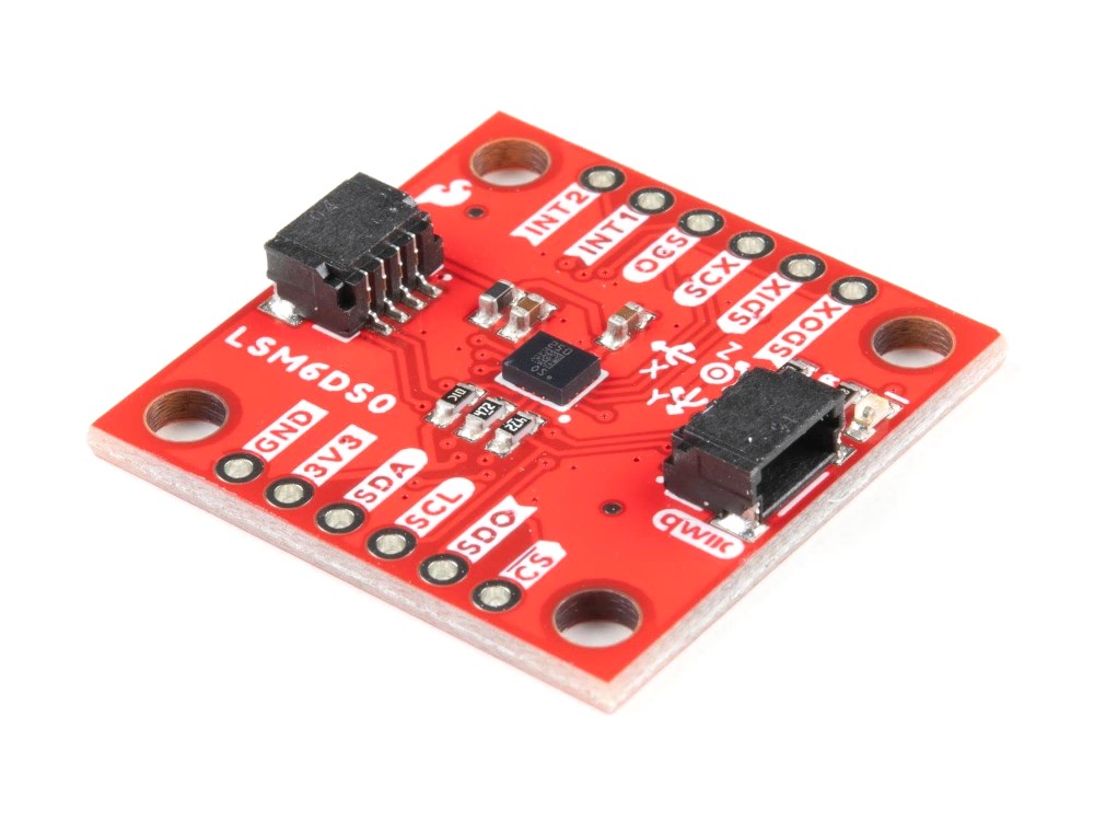
SparkFun 6 Degrees of Freedom Breakout - LSM6DSO (Qwiic)
- Brands Sparkfun Code: SN-QW-LSM6D
Availability: 8
Your shopping cart is empty!
The SparkFun LSM6DSO 6 Degrees of Freedom Breakout is an accelerometer and gyroscope sensor with a giant 9kB FIFO buffer and embedded processing interrupt functions. Due to the capabilities and low cost of the LSM6DSO we've created this small breakout board just for you! Each LSM6DSO breakout has been designed to be super-flexible and can be configured specifically for many applications. With the LSM6DSO breakout you will be able to detect shocks, tilt, motion, taps, count steps, and even read the temperature!
The LSM6DSO from STMicroelectronics is capable of reading accelerometer and gyroscope data up to 6.66kHz for more accurate movement sensing. As stated before this breakout also has the ability to buffer up to 9kB of data between reads, host other sensors, and drive interrupt pins all thanks to the LSM6DSO's built-in FIFO.
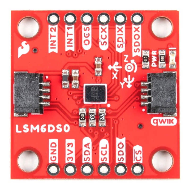
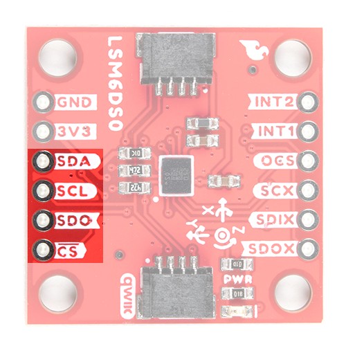
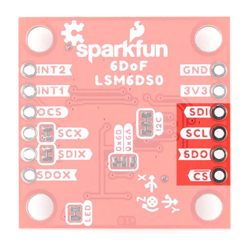
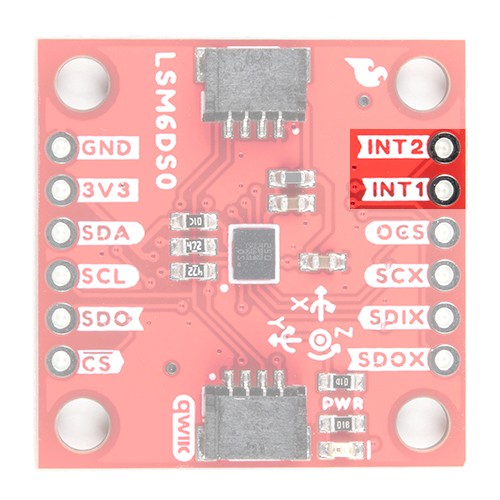
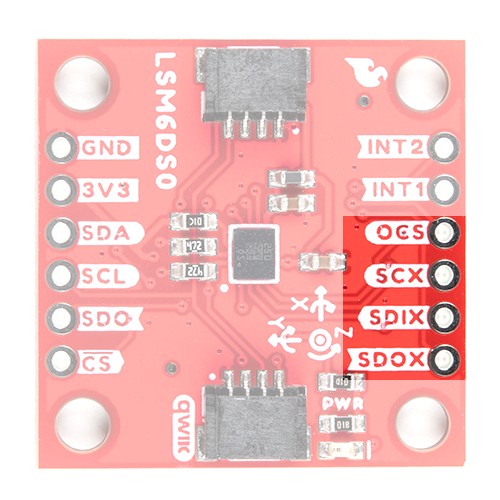
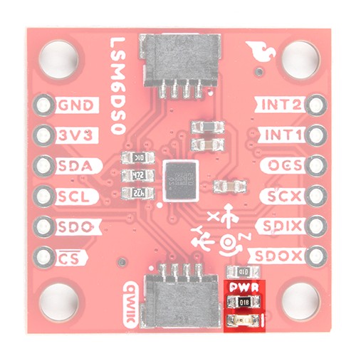
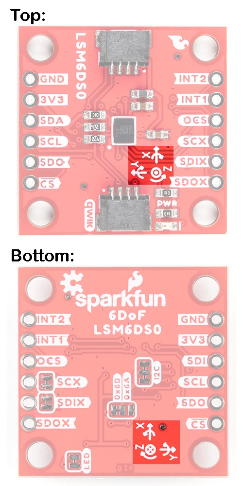
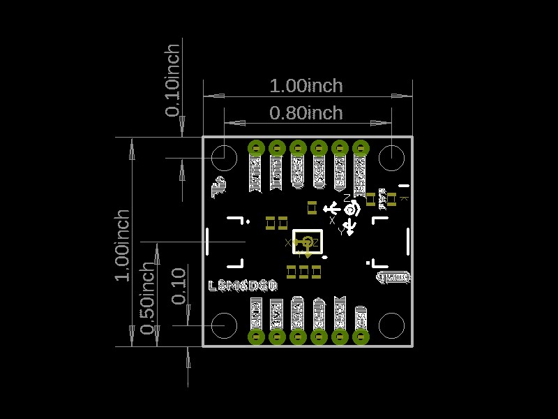
Utilizing our handy Qwiic system, no soldering is required to connect it to the rest of your system. However, we still have broken out 0.1"-spaced pins in case you prefer to use a breadboard. Each pin has been broken out on the LSM6DSO, with one side of the board featuring power, I2C, and SPI functionality while the other side sporting pins that control auxiliary functionality and interrupt outputs.
Note: The LSM6DSO is a 3.3V device so supplying voltages greater than ~3.6V can permanently damage the IC. A logic level shifter is required for any development platform operating at 5V.
We recommend powering the board through the Qwiic connector when quickly prototyping. For a more secure connection, you can always solder to the plated through-holes labeled 3V3 and GND. The recommended input voltage when using the board with a microcontroller is 3.3V if you are using the Qwiic connector. However, you can use a regulated supply voltage between 1.71V and 3.6V to power the sensor. The logic levels will match the input voltage (e.g. if the sensor is powered at 3.3V, the logic level will be 3.3V as well).
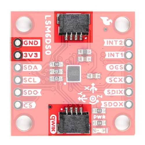
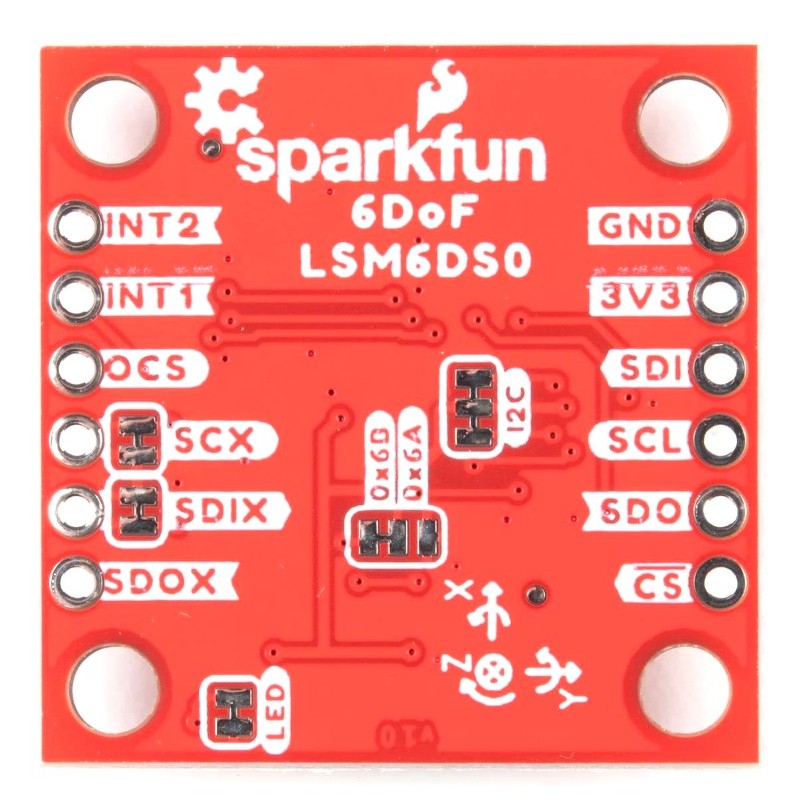
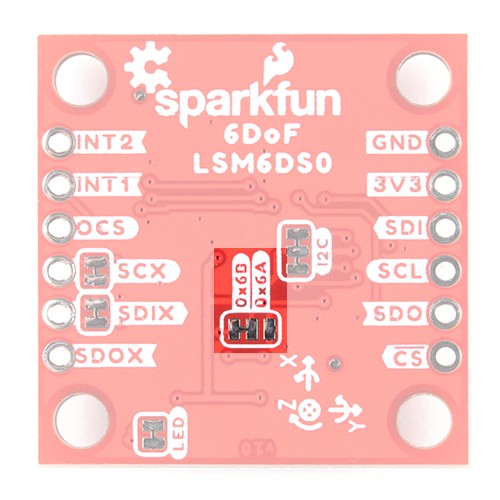
The main method of reading the LSM6DSO is through the I2C bus. The board includes two Qwiic connectors for fast prototyping and removes the need for soldering. All you need to do is plug a Qwiic cable into the Qwiic connector and voila! You can also solder to the plated through-holes labeled as SDA and SCL as an alternative. The default address for the IC is 0x6B. However, you can adjust the jumper on the back of the board to change the address to 0x6A.
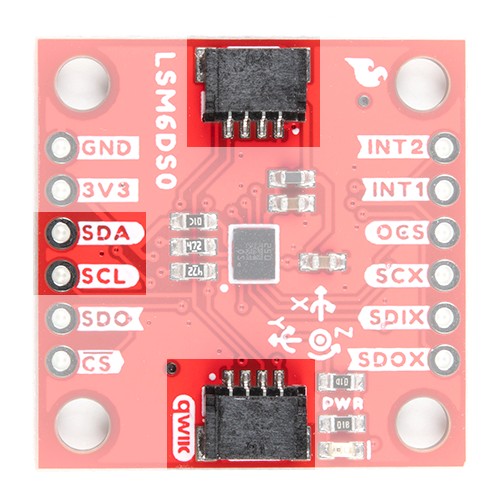
If you decide to use a SPI bus, you will need to solder header pins or wires to the board.
When using the board in SPI mode, you will need to cut the I2C jumper for the default address (e.g. 0x6B) on the back and leave the jumper pads unconnected when using SPI.
INT1 and INT2 are programmable interrupts for the accelerometer and gyroscope. They can be set to alert on over/under thresholds, data ready, or FIFO overruns. Make sure these are connected to an INPUT pin to prevent driving 5v back into the LSM6DSO.
There are a variety of interrupts on the LSM6DSO. While connecting these is not as critical as the communication or power supply pins, using them will help you get the most out of the chip.
The interrupt pins are INT1 and INT2. One or both pins can be software configured and mapped to the following conditions:
Only a few interrupt examples are provided. See the datasheet and application guide for using the advanced interrupt features.
The auxiliary serial data output pins are used to attach slave I2C and auxiliary SPI 3/4-wire devices for FIFO data collection. This function is not covered in this tutorial.
There are five jumpers on the back of the board. For more information, check out tutorial on working with jumper pads and PCB traces should you decide to cut the traces with a hobby knife.
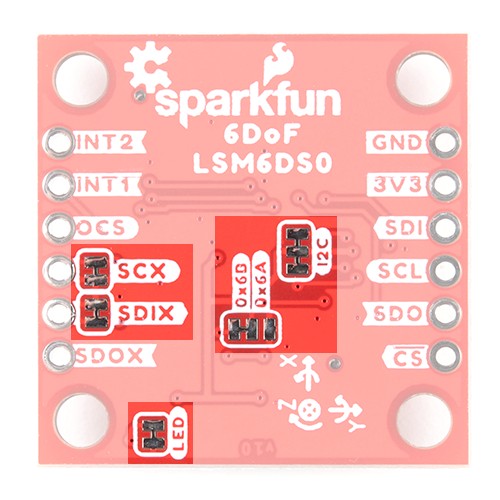
The board includes an LED indicator that lights up when there is power available.
For easy reference, we've documented the 6DoF's vectors with 3D Cartesian coordinate axes on the top and bottom side of the board. Make sure to orient and mount the board correctly for your application. Remember, it's all relative.
Some of the things the LSM6DSO can do: