 International
 Singapore
 Malaysia
 Thailand
 Vietnam
Your shopping cart is empty!

3D Printed Self Watering Pot Featuring Maker Soil Moisture Sensor
Overview
In this tutorial, we will make a project using the Maker Soil Moisture Sensor. Utilizing the disable pin of the sensor, we will make the project with power saving mode in mind.
Components Used
Preparation
Software you might need:
- Autodesk Fusion 360 (Register as hobbyist/student/educator)
- Ultimaker Cura
- Mu Editor
Design files can be found here: https://www.thingiverse.com/thing:5278599
- SelfWateringPotPot.stl - Print it upside down without support.
- SelfWateringPotPotwithDrainageHoles.stl - Print it upside down without support. The drainage holes need to be punctured manually after printing. Some kind of garden mesh sheet is recommended before putting in soil to avoid too much dirt going into the reservoir, clogging the water pump.
- SelfWateringPotReservoir.stl - Print with default orientation. You can modify the openings for your display of choice (use Fusion360 and open .f3z file).
- SelfWateringPot.f3z - Open with Fusion 360. You can modify the mounting holes for the Maker Pi RP2040 if you prefer using other microcontrollers. Remember to include some kind of motor driver with your microcontroller. You can modify the OLED mount on the pot part and the openings on the reservoir part to suit your display of choice.
Slice the .stl files in Cura with these settings:
- Layer Height: 0.2mm
- Perimeter Count: 5
- Top/Bottom Layer Count: 5
- Infill: 20%
- Temperature: 180°C / 60°C
Assembly
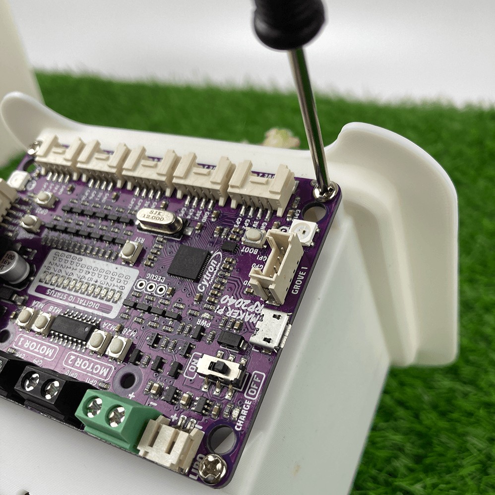
1. Mount the Maker Pi RP2040 to the pot using M3 screws.
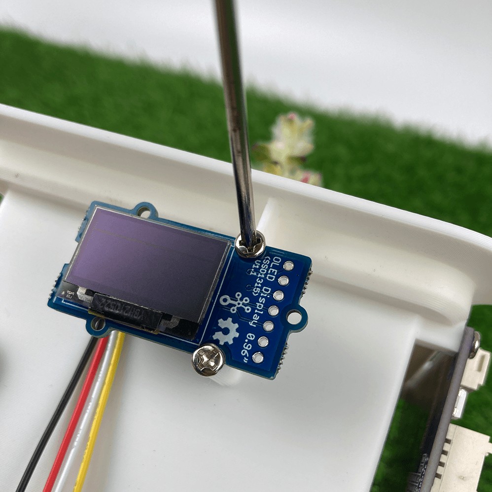
2. Mount the Grove Oled to the pot using M3 screws.
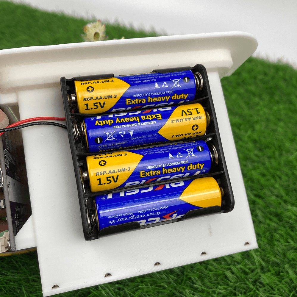
3. Attach the 4xAA Battery Holder to the pot using double sided tapes.
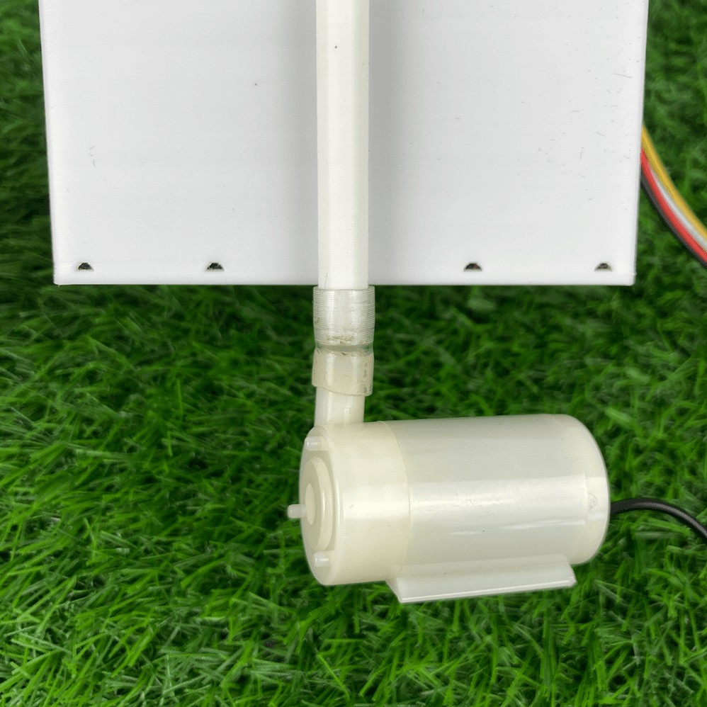
4. Cut the water pump tube and attach the pump to the pot as below.
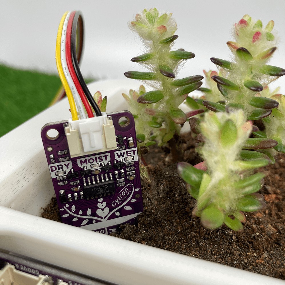
5. Insert the Maker Soil Moisture Sensor into the Soil.
6. Connect the Grove Oled to Grove 1 port of the Maker Pi RP2040
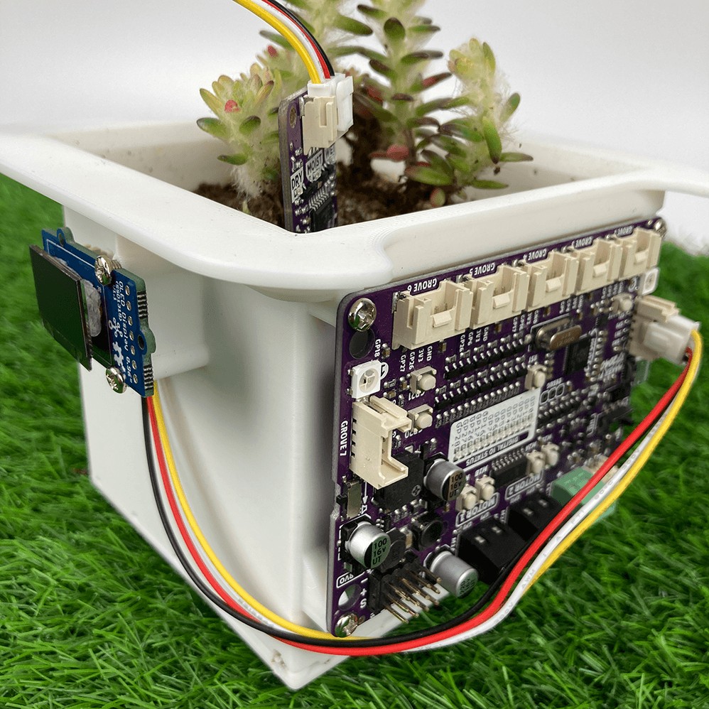
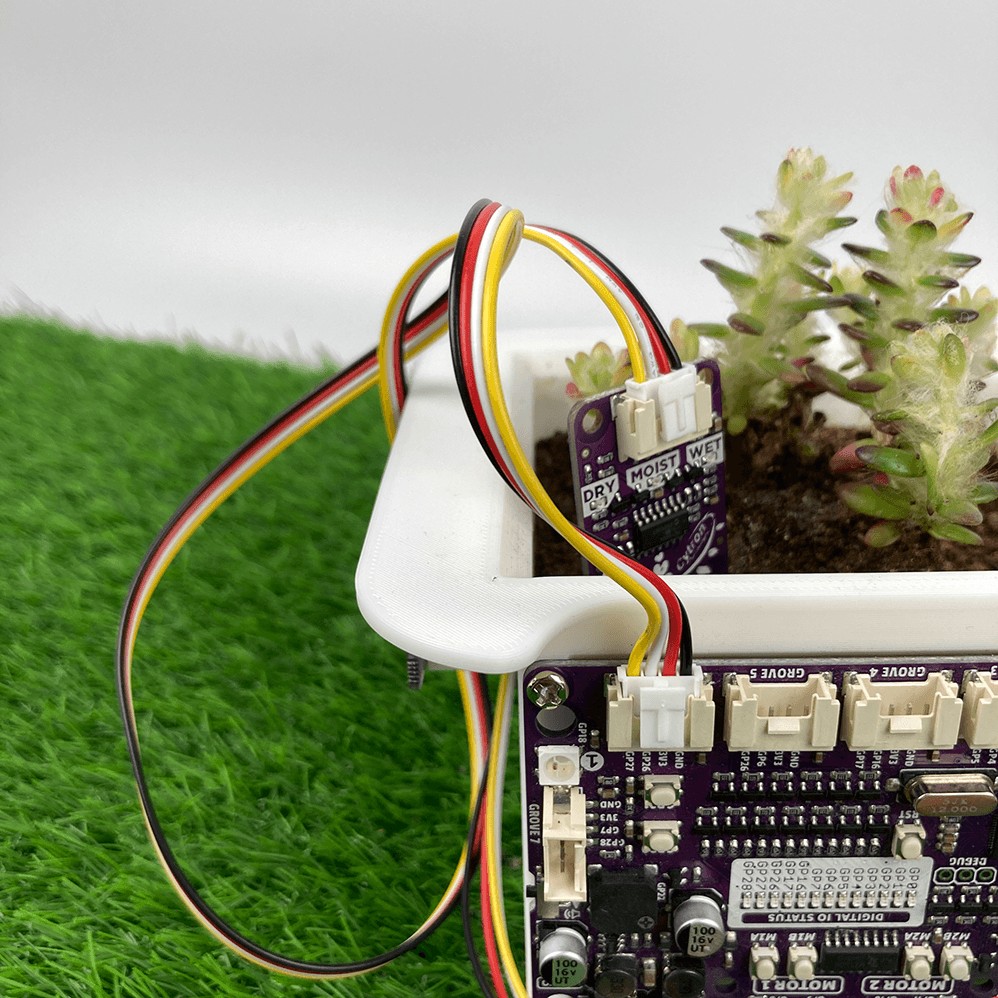
7. Connect the Maker Soil Moisture Sensor to the Grove 6 port of the Maker Pi RP2040
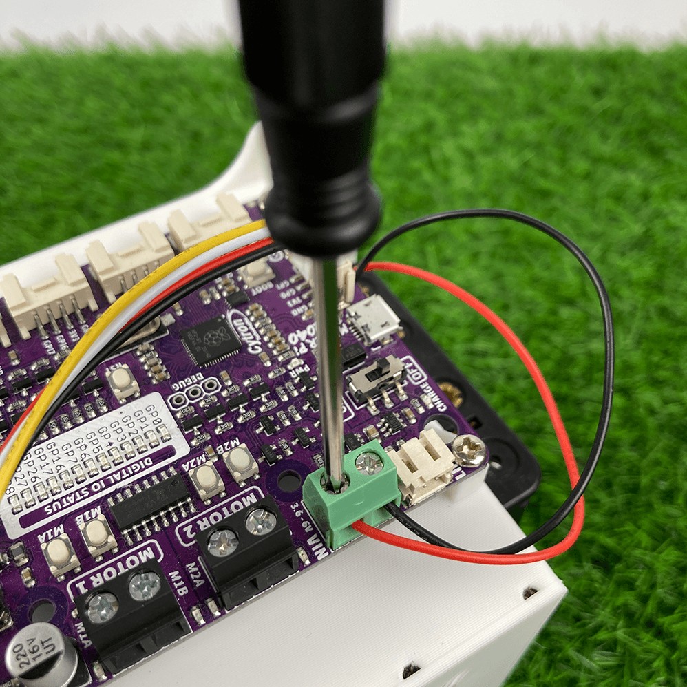
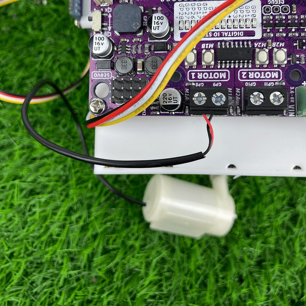
8. Connect the battery terminals to the VIN screw terminals of the Maker Pi RP2040
9. Connect the water pump terminals to the Motor 1 screw terminals of the Maker Pi RP2040
Coding
Download the CircuitPython library bundle here. Transfer these into the lib folder of the Maker Pi RP2040 (if you're using the same display as the tutorial).
- adafruit_display_text
- adafruit_displayio_ssd1306.mpy
Sensor Only
import time
import board
import analogio
Sensor = analogio.AnalogIn(board.GP27)

# For good accuracy, please determine these two values.
Wet = 1.444         # Voltage when in air
Dry = 2.333         # Voltage when fully submerged in water

Voltage = 0.0       # Voltage value
Moisture = 0.0      # Moisture percentage

while True:
    Voltage = (Sensor.value * 3.3) / 65536
    Moisture = (1-(Voltage-Wet)/(Dry-Wet))*100
    print(str("{:.2f}".format(Moisture)) + "%" + "\t" + str("{:.3f}".format(Voltage)) + "V")
    time.sleep(0.1)
Full Project
import time
import board
import digitalio
import analogio
import displayio
import terminalio
from adafruit_display_text import label
import busio
import adafruit_displayio_ssd1306
import pwmio
from adafruit_motor import motor


# Setup Water Pump
PWM_M1A = board.GP8
PWM_M1B = board.GP9
M1A = pwmio.PWMOut(PWM_M1A, frequency=10000)
M1B = pwmio.PWMOut(PWM_M1B, frequency=10000)
motor1 = motor.DCMotor(M1A, M1B)

# Setup OLED
displayio.release_displays()
i2c = busio.I2C(board.GP1, board.GP0)
display_bus = displayio.I2CDisplay(i2c, device_address=0x3C)
WIDTH = 128
HEIGHT = 64
BORDER = 5
display = adafruit_displayio_ssd1306.SSD1306(display_bus, width=WIDTH, height=HEIGHT)

# Setup sensor pins
Disable = digitalio.DigitalInOut(board.GP26)
Disable.direction = digitalio.Direction.OUTPUT
Sensor = analogio.AnalogIn(board.GP27)

# Tolerance to prevent Moisture lvl >100% or <0%.
Tolerance = 0.050

# Time to wait for sensor to stabilize (seconds).
StabilizeDelay = 3

# Time for one watering cycle (seconds).
WateringDuration = 10

# For good accuracy, please determine these two values.
Wet = 1.400 - Tolerance  # Voltage when in air.
Dry = 2.300 + Tolerance  # Voltage when fully submerged in water.

Voltage = 0.0  # Voltage value.
Moisture = 0.0  # Moisture percentage.

while True:
    TimeRemain = 86400  # 86400 seconds in 1 day
    Disable.value = False  # Turn on the sensor.
    time.sleep(StabilizeDelay)  # Wait for sensor to stabilize.
    TimeRemain = TimeRemain - StabilizeDelay  # Subtract delay time.
    Voltage = (Sensor.value * 3.3) / 65536  # Read sensor value, convert to voltage.
    Moisture = (
        1 - (Voltage - Wet) / (Dry - Wet)
    ) * 100  # Convert voltage to moisture percentage.

    # Print values to serial monitor.
    print(str("{:.2f}%\t".format(Moisture)) + str("{:.3f}V".format(Voltage)))

    # Display values on OLED
    text = (
        "Moisture Lvl:\n"
        + str("{:.2f}%\n".format(Moisture))
        + str("{:.3f}V".format(Voltage))
    )
    text_area = label.Label(
        terminalio.FONT, text=text, color=0xFFFFFF, x=28, y=HEIGHT // 2 - 1
    )
    display.show(text_area)

    if Moisture < 15.0:
        motor1.throttle = 0.7
        time.sleep(WateringDuration)
        TimeRemain = TimeRemain - WateringDuration
        motor1.throttle = 0

    Disable.value = True  # Turn off the sensor.
    time.sleep(TimeRemain)  # Sleep for 1 day (86400 seconds) - MCU on low power mode.
Things to note
- Depending on your 3D printing filament, the double-sided tape might not stick properly. You might consider modifying the design to hold your battery holder more securely.
- Be mindful of the water level when pouring water into the reservoir, since there is no mechanism to prevent water from overflowing into the electronics.
- Some kind of garden mesh sheet is recommended before putting in soil to avoid too much dirt going into the reservoir, clogging the water pump.
Tips on Power Saving
- Instead of using time.sleep(), you can refer to this link to try using the deep sleep command for CircuitPython.
- Some MCU like the RP2040 cannot hold the disable pin HIGH when in deep sleep mode. There's a workaround for this problem, which is by connecting the disable pin to 3.3V through a 10k Resistor (pull-up resistor). This will ensure that the sensor is disabled by default, so you have to send a low voltage in order to read the value from the sensor.
- When in sleep modes, the power LEDs and the LED indicators will consume a significant amount of power. You can de-solder them, but soldering them back on will be a challenge if you're hand soldering.
References
- alarm – Alarms and sleep — Adafruit CircuitPython 7.3.0-alpha.0 documentation
- CytronTechnologies/MAKER-PI-RP2040: MAKER-PI-RP2040 | Simplifying RP2040 for Robotics (github.com)
- CircuitPython Usage | Monochrome OLED Breakouts | Adafruit Learning System
- MAKER-SOIL-MOISTURE Datasheet - Google Docs
- Pull-up Resistors - learn.sparkfun.com