 International
 Singapore
 Malaysia
 Thailand
 Vietnam
Your shopping cart is empty!

Quadruped Robot with SC08A Servo Controller
- Hussien Jawhar Sathik
- 20 Sep 2022
- Tutorial
- 1023
Introduction
What is Quadruped robot? A quadruped robot has only four servomotors to actuate four legs. Therefore the movements to generate the locomotion of each leg were realized by using link mechanism. One of the famous robot using the concept of quadruped is the spider robot. The most interesting part to watch on the spider robot is its movement. And building one by yourself, it sounds cool right? Well, in this tutorial today, we would like to see how to build the robot from the scratch.
Getting Started
To build this robot, there are quite a number components and 3d printed parts are required. Hence this will be separated into two two different parts. First we will look at the components, and next we will look at the 3d printed parts.
Components
Below is the list of the components that are needed to build this robot.
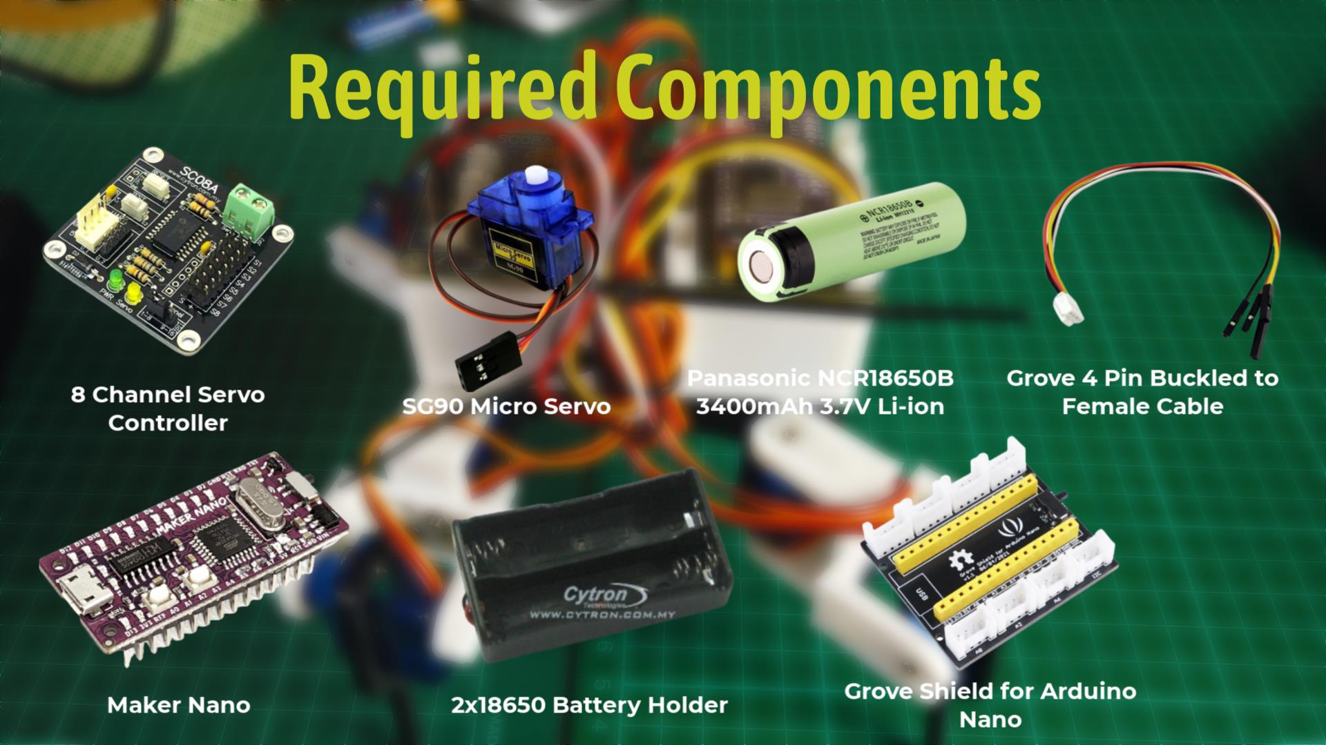
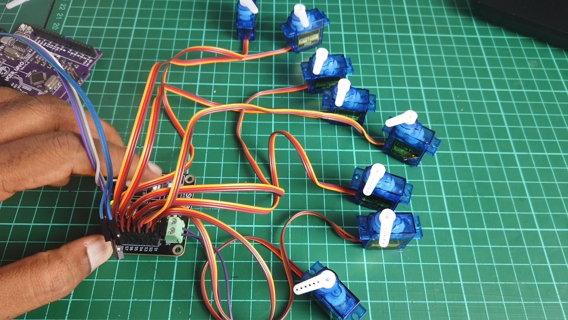
Among all the component listed above, one of the components that i would like to explain detail is the 8 Channel Servo Controller.
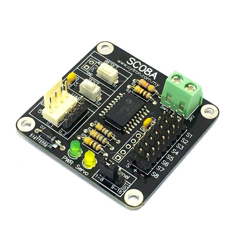
This device is also known as the SC08A. SC08A offers reliable yet user friendly RC servo motor controller to hobbyist and students. This SC08A can control 8 channels of servo simultaneously. One of the advantage of the SC08A over SC16A is, user is able to deactivate any servo channel at any time and user can even set the initial position of any channel at the next start-up. Each servo signal pin is able to generate servo pulses from 0.5 ms to 2.5 ms, which is greater than the range of most servos, further allows for servos to operate 180 degrees. SC08A comes with small size and different protocol compares to SC16A.Through serial communication, SC08A can be daisy chain in 2 boards to offer independent control over 16 RC servo motors simultaneously. The host of SC08A can either be a PC desktop/Laptop with USB to serial(UART) converter, or microcontroller with UART interface. UART interface present a flexible, fast and easy to use a feature. That is about the SC08A.
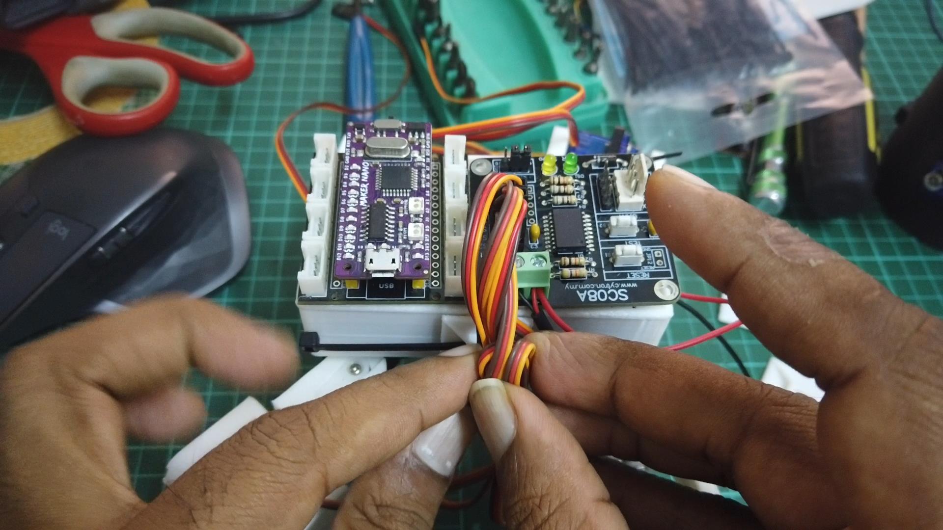
The connection between the components are done as shown in the figure below
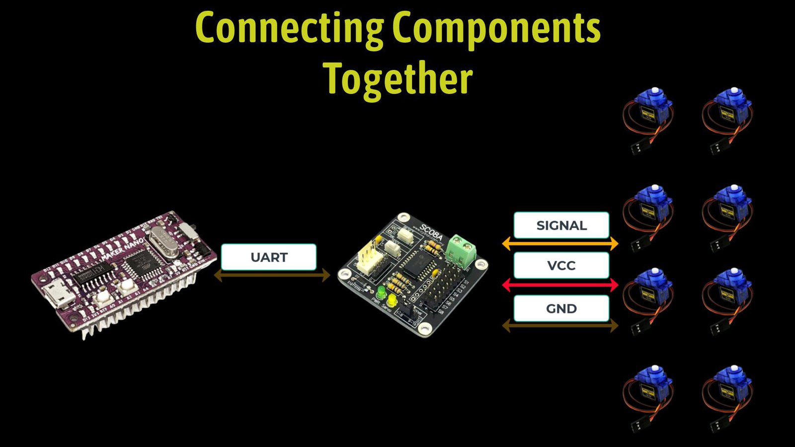
The connection between the devices are straight forward. As for the connection, we use the serial communication (UART) to communicate between the Maker Nano and the SC08A servo controller. The last component to connect is the battery to power the servo controller and the Maker Nano. For this i have used the 18650 battery with the holder. I have looped the power output so that this single power source can power the Maker Nano and also the SC08A. Now we are done with the electronics part, we can move to the 3D printed parts.
3D Printed Parts
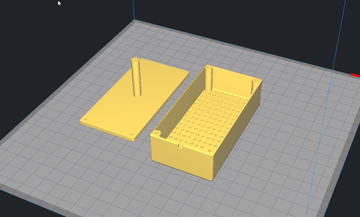
This project is build using 3D printed parts. The 3D printed parts for this project can be downloaded from the Thingiverse @ https://www.thingiverse.com/thing:38159. Printing this part are straight forward as it does not need any special settings. I printed the parts using Artillery Hornet and the output is quite decent. Below are some of the 3D printed parts picture.
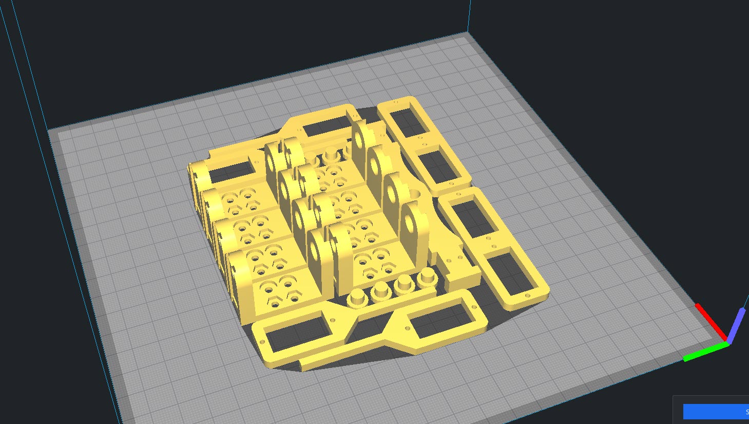
This are the parts that can be downloaded from the Thingiverse link. Apart from this i have created a small casing to hold the battery and also to mount the other devices. Below is the 3D view of object.
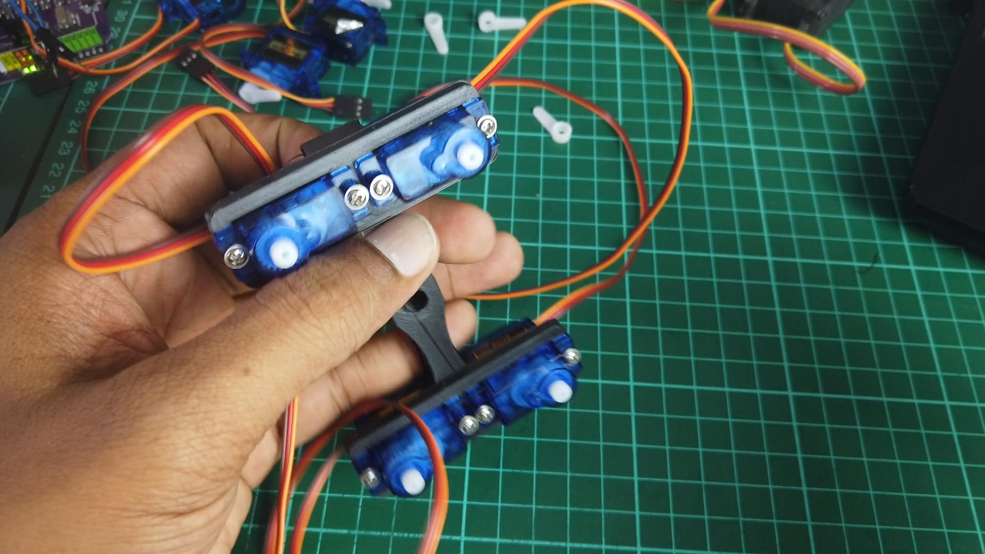
Assembling The Robot
The assembling of the robot is as shown in the video. Here are some of the screenshot of assembling the robot.
Coding
For the coding, i have developed using the example code provided for the SC08A. This code basically moves the spider bot ahead.
const char tx = 1;


void setup()
{
  Serial.begin(9600);
  pinMode(tx, OUTPUT);
  on_off_motor(0,1);
  steady_position();
  delay(1000);
}

void loop()
{
  move_forward1();
  delay(500);
  steady_position();
  delay(1000);
  move_forward2();
  delay(500);


void on_off_motor(unsigned char channel, unsigned char on)
{
  unsigned char first_byte =0;
  first_byte = 0b11000000 | channel;
  Serial.write(first_byte);
  Serial.write(on);
}

void set_ch_pos_spd(unsigned char channel, unsigned int position, unsigned char velocity)
{
  unsigned char first_byte = 0;
  unsigned char high_byte = 0;
  unsigned char low_byte = 0;
  first_byte = 0b11100000 | channel;
  high_byte = (position >> 6) & 0b01111111;
  low_byte = position & 0b00111111;
 Serial.write(first_byte);
  Serial.write(high_byte);
  Serial.write(low_byte);
  Serial.write(velocity);
 }

 void steady_position()
 {

     set_ch_pos_spd(2, 4000, 30);
    set_ch_pos_spd(4, 4000, 30);
    set_ch_pos_spd(6, 4000, 30);
    set_ch_pos_spd(8, 4000, 30);

    set_ch_pos_spd(1, 2000, 30);
    set_ch_pos_spd(3, 1500, 30);
    set_ch_pos_spd(5, 2500, 30);
    set_ch_pos_spd(7, 6500, 30);
 }

 void move_forward1()
 {
 set_ch_pos_spd(2, 2000, 60);
  set_ch_pos_spd(1, 2500, 60);

  set_ch_pos_spd(6, 5000, 60);
  set_ch_pos_spd(5, 1500, 60);
 }

 void move_forward2()
 {
   set_ch_pos_spd(4, 6000, 60);
   set_ch_pos_spd(3, 2000, 60);

   set_ch_pos_spd(8, 6000, 60);
   set_ch_pos_spd(7, 7000, 60);


 }
Video
Thank You
Thanks for reading this tutorial. If you have any technical inquiries, please post at Cytron Technical Forum.
"Please be reminded, this tutorial is prepared for you to try and learn.
You are encouraged to improve the code for a better application."