PIC16F VS PIC18F:Analysis of PIC Mid-Range 8 bit family and Advanced 8-bits Family

PIC16F VS PIC18F:Analysis of PIC Mid-Range 8 bit family and Advanced 8-bits Family

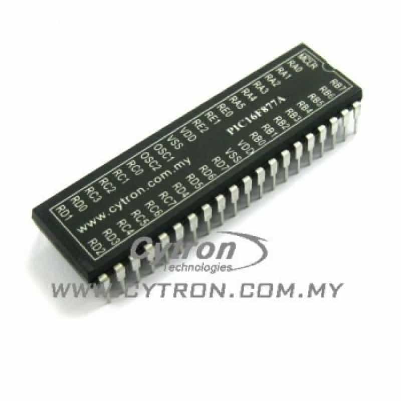
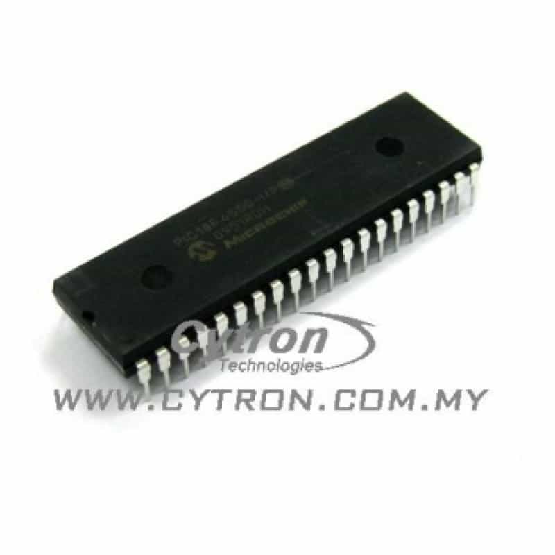
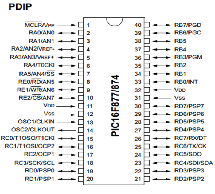
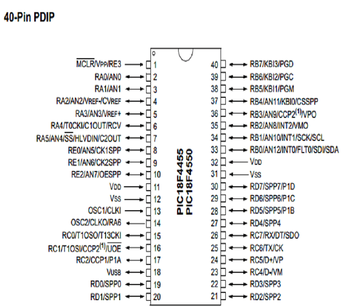
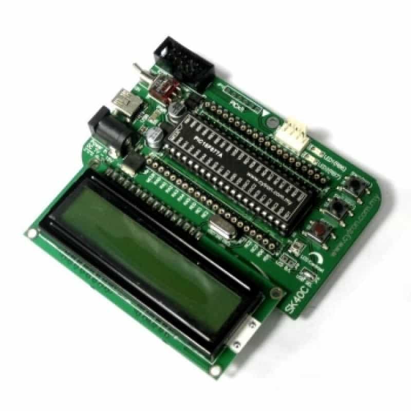
PIC Microcontroller is one of the popular device among student and hobbyist. Microchip Technology is a giant for embedded system. Every year, they produce different product for different application range from beginner training kit  to advanced application such as medical instrumentation and robotic. A lot of people wonder which device should start with when exploring PIC MCU? So in this tutorial, i will guide you the software and hardware features of 2 PIC families :Mid-range 8 bit MCU(PIC 16 series) and Advanced 8 bits MCU(PIC18 series)

SOFTWARE USED FOR THIS DISCUSSION

  • MPLAB X
  • XC 8 C Compiler

In our discussion, PIC16F877A will  represent 8-bit mid range MCU and PIC18F4550 will represent 8-bit advance MCU. This is because both devices very famous among their respective family and  user 

1) OVERVIEW


FEATURES

  • Pin Count: 40-pin PDIP
  • I/O PIN : 33
  • Program Memory: 14KB or 8K 14-bit Flash
  • Max Crystal Speed: 20MHz
  • Internal Oscillator : No
  • RAM Bytes: 368
  • EEPROM (Bytes): 256
  • Timers: 2 x 8 bit, 1 x 16-bit
  • Serial Communication: 1xUSART, 1 x MSSP(SPI/I2C)
  • Capture/Compare/PWM: 2 x CCP
  • ADC: 8ch, 10-bit
  • Comparators: 2

FEATURES

  • Pin Count:  40-pin PDIP
  • I/O PIN : 35
  • Program Memory  32 KB Flash  
  • Max Crystal Speed: 48MHz or 12 MIPS
  • Internal Oscillator : 31kHz to 4Mhz
  • EEPROM (bytes):  256
  • Timers:  1 x 8-bit, 3 x 16-bit
  • Serial Communication Peripherals:  1-EUSART, 1-MSSP(SPI/I2C)
  • ADC:  13 ch, 10-bit
  • Capture/Compare/PWM Peripherals:  1 CCP, 1 ECCP
  • Comparators:  2
  • Special features: USB (ch, speed, compliance):  1, Full Speed, USB 2.0
 

2) I/O PORT

The number of  I/O Port of PIC18F4550 is 35 and the number of I/O Port of PIC16F877A is 33. Well, the major difference of I/O Port of these two PIC microcontroller is the register. PIC18F4550 consists of “LAT ” register but PIC16F877a only consists of “PORT” register and “TRIS” register

The “LAT” Register  is useful register for read-modify-write operations on the value that I/O Pins are driving.

The figures below show the pin layout for both PIC.

PIC16F877A

PIC18F4550

The Pin 18 of PIC18F4550 is reserve for USB function while Pin 18 of PIC16F877A can perform multi-function. Due to this unique design, PIC18F4550 don’t have RC3 I/O


3) PIC MCU CONFIGURATION BIT

When programming the PIC microcontroller, certain operational modes must be set prior to the main program download. These are controlled by individual bits in a special configuration register separated from the main memory block. The main options are as follows:

  • Clock Source
  • Watchdog Timer
  • Power-Up timer
  • Brown-out reser
  • Low-Voltage programing

If you are using PIC16F877A ,general  configuration bit above is enough to begin your project. But if you are using PIC18F4550, you will need to configure certain data bit if  user require to apply  the unique feature of PIC18F4550 such as internal oscillator and USB module

Section 3.1 and 3.2 will explain on how to configure Internal oscillator and USB module of PIC18F4550

3.1) DISCOVER INTERNAL OSCILLATOR FOR PIC18F4550

PIC18F4550 datasheet description Internal Oscillator modes

STEP 1

PIC16F877A don’t have any internal oscillator , clock source of PIC16F877A is depends on external oscillator. PIC18F4550 consist of build in internal oscillator. The frequencies internal oscillator range from 31kHz to 8MHz. In order to initialize internal oscillator, configure the clock source to internal oscillator modes. There are 4 different modes available as stated in datasheet page number 27


Internal Oscillator frequencies configuration

STEP 2

After you set clock source to internal oscillator , you need configure IRCF of OSCON data bit to desire frequencies  as state in datasheet . Once this data bit configured, PIC18F4550 will operate with internal oscillator.I set the IRCF data bit using public function, you can configure the IRCF data pin directly in the main function 

3.2) INITIALIZE USB MODULES FOR PIC18F4550

To initialize USB modules of PIC18F4550, we must have a very good understand of PIC18F4550 clock diagram especially the primary oscillator.

First we must configure clock source to “HSPLL_HS” .

When discussing about USB module, we must consider the frequencies of  external oscillator. For example, let say we are using 20Mhz crystal. To initialize the USB module,first we must  configure the 3 bit PLLDIV data bit to produce output of 4MHz.To do so, configure  PLLDIV=5.Subsequently, configure USBDIV data bit into 2.This is to let USB clock source came from amplified input frequencies.

The CPU of micrcontroller also using the input frequncies. Although 20MHz input Oscillator is used. We still can use maximum frequencies by configure CPUDIV data pin into “OSC1_PLL2”

After required configuration bit is select for USB configuration. Your USB module is good to go

4) ADC ARCHITECTURE AND ADC BIT CONFIGURATION

In discussion of concept of ADC in PIC MCU, reference voltage of MCU is a very important point.This is because ADC involves reference voltage in converging analog input into digital data.Resolution of 10 bit of ADC  represents by 2 power of 10 which equal to 1023 and if reference voltage is base on Vdd and Vss which is 5V and ground respectively. The ADC step side= 5/1023= 4.88mV

What is that mean? It means for every 1 bit of ADC resolution, it consists of  approximately 4.88mV. Before we can discuss about voltage reference bit . Let discuss about ADC architecture of the devices 

ADC Architecture of PIC16F877A

ADC bit configuration of PIC16F877A

  • A/D conversion clock(ADCS)
  • A/D Port Configuration Control bits(PCFG)
  • A/D Result Format Select bit(ADFM)
  • Analog Channel Select Bit(CHS)
  • ADC module Switch(ADON)
  • ADC Module Switch(ADON)
  • GO/DONE Bit

ADC architecture of PIC18F4550

ADC bit configuration of PIC18F4550

  • Voltage Reference Configuration Bit (VCFG)
  • A/D conversion Clock(ADCS)
  • A/D Port Configuration Control Bits(PCFG)
  • A/D Result Format Select Bit(ADFM)
  • Acquisition Time Selection Bit(ACQT)
  • Analog Channel Select Bit(CHS)
  • ADC Module Switch(ADON)
  • GO/DONE Bit

4.1) PCFG OPTION

PCFG bit is the data that define role of Analog Channel to Digital input or Analog input .The PCFG configuration of PIC18F4550 independent of Reference voltage bit

  • PIC16F877A PCFG option.
  • PIC18F4550 PCFG option

4.2) VOLTAGE REFERENCE BIT (VCFG)

I used to mention important of Voltage reference bit at the beginning of this topic. As you can see from PCFG option above. PIC16F877A Voltage reference bit is depends on PCFG option. But for PIC18F4550, you can choose your PCFG option without affecting voltage reference bit. The Voltage reference bit of PIC18F4550 as shown in picture below


5) INSTRUCTION SET

The most obvious difference between PIC16F877A and PIC18F4550 is the assembly language component of the device From Byte-Oriented operation, Bit-Oriented operation,Literal operation and Control Operation.PIC18F4550 provide more instructions compare to PIC16F877A.

PIC16F877A Control and Literal operation Instruction Set

PIC18F4550 Control Operation instruction Set

6) CCP MODULE

The last discussion of both PIC MCU is  CCP module. Well, both devices consists of two CCP channel. The major difference among them is PIC18F4550 consists of one ECCP module.

PIC18F4550 ECCP block diagram

ECCP module is definitely a highlight of PIC18F4550. The  ECCP mode provides additional PWM output options for a wider range of control applications. The module is a backward compatible version of the standard CCP module and offers up to four outputs, designated P1A through P1D

Although we know there is two CCP channel in PIC18F4550 datasheet .It is not possible to use ECCP and CCP at the same time.  This is the reason why PIC18F4550 only consist of one CCP and one ECCP channel.

7) ALL IN ALL………………………

As we can expect, the advanced 8 bit MCU PIC18F4550 really surpass the PIC16F877A  on every perspective. With the nano-watt technology companion, it makes PIC18F4550 a better option than PIC16F877A. Am I saying PIC16F877A should be replace by PIC18F4550 ? Definitely NO! It all depends on the application we need to achieve because as a  beginner or intermediate level user. It is very hard to fully utilized available function of a microcontroller

GETTING STARTED ? LET’S TRY SK40C  

If you are a beginner for PIC MCU. I highly recommend you start with our starter kit SK40C

Our starter kit support 40-pin PDIP device. Please check out  the user manual .Beside that, we do offer combo kit! Click here for PIC16F877A series andhere for PIC18F4550 

BUY