Your shopping cart is empty!
COMPONENT NEEDED
In this project, we are going to do a simple LEDs blinking using the LEDs on SK40C. In here, we are using both of the LEDs and blink it like a police car. Besides on learning electronic parts, you will also learn about some coding in C using HI-TECH C in MPLAB.
You can get the component here:
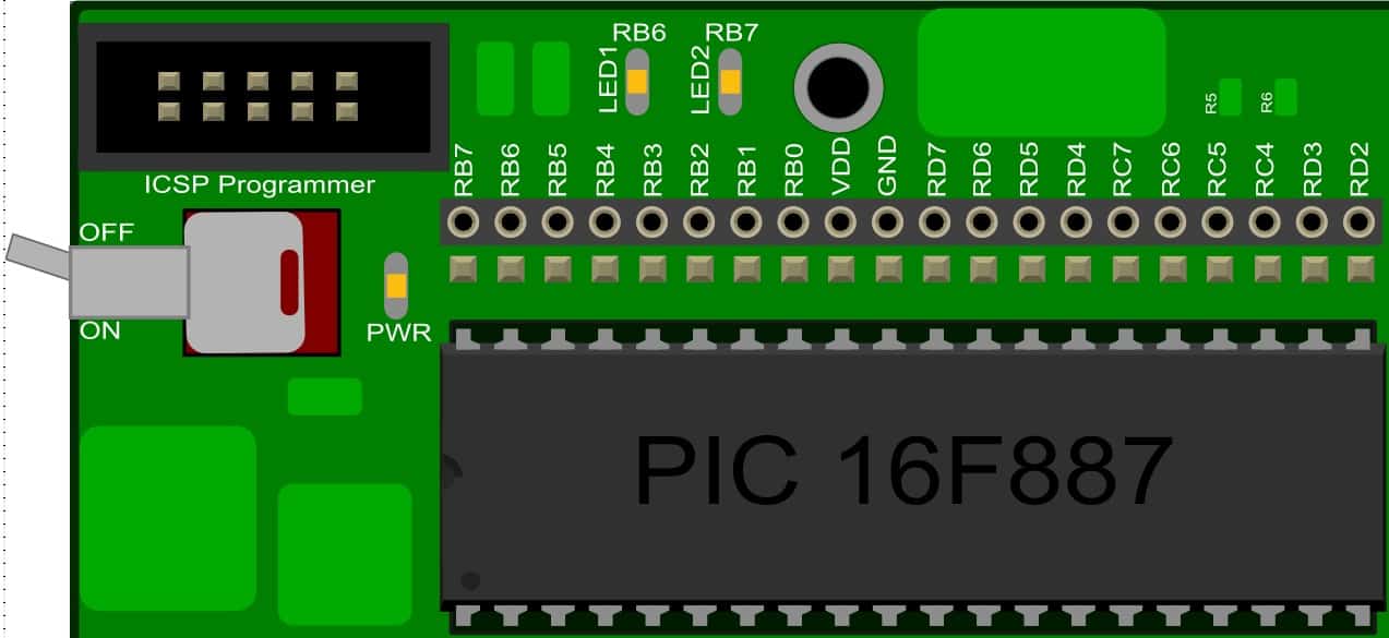
Connection LEDs on SK40C
For this project, the LEDs was already connected to the pins RB6(PORTB.6) and RB7(PORTB.7). So, you may only have to configure the I/O pins as an output in programming part. To program the PIC16F887, connect the UIC00B to the ICSP Programmer. Make sure the power connection is correct and ON for SK40C. Open MPLAB and include the Project_0.c and click to compile and build .HEX file. After “Build Successful”, the PICKit2 should automatically run and program the .HEX file into PIC16F887. Finally, the LED1 and LED2 will be blink like the police car.
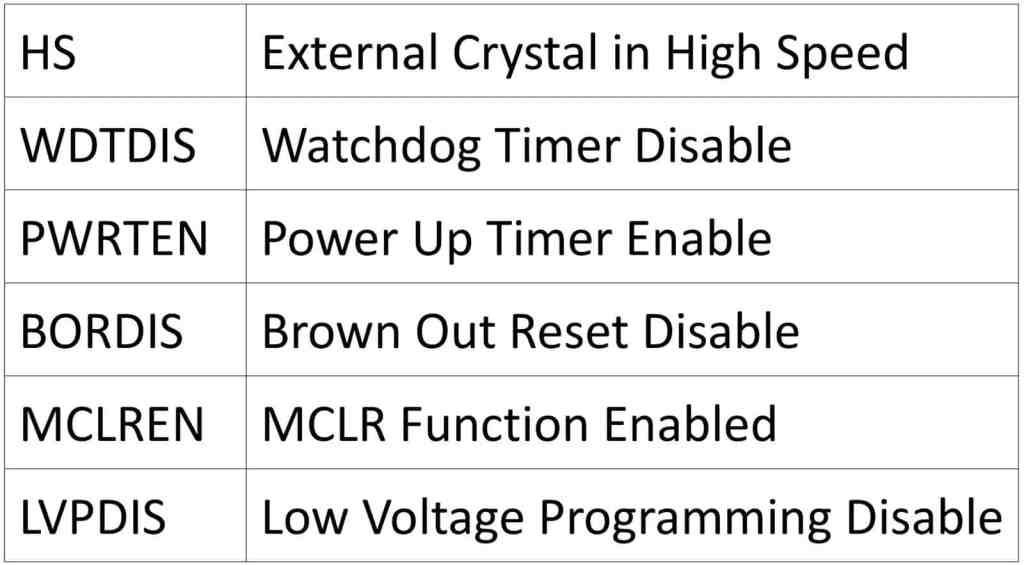
Configuration for PIC16F887
Figure below shows the Configuration for PIC16F887. The code above can be found at the Configuration bits (CONFIG1) in PIC16F887 data sheet
CODE OVERVIEW
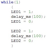 |
while(1)
To make the program loop forever, we use while(1) function. while construct consists of a block of code and a condition. The condition is evaluated, and if the condition is true, the code within the block is executed. In here, we put (1) to indicated that the condition is true.
delay_ms(100);
is a function call is an expression containing a simple type name and a parenthesized argument list. The argument list can contain any number of expression separated by commas. It can also be empty. In here, we put the arguments list as 100 which is 100ms.
Comment line //
In the code, we can found the // on the right hand side of the code. The // is simply a comment in the code and is ignore by the compiler.
Any code that behind the // is ignore by compiler and is just simply there for you, or everyone to reads the code. Comments are essential in the code to help you to better understanding on what going on and how the code works. Comments can be put after the command as in the next line of the program.
On the other hand, you can also put comments into the block statement by using /* and */.
E.g.:
/* All the code within the slash and asterisks will be ignore by compiler */
void delay_ms(unsigned int ui_value)
is an function that will be call and perform in the main function. “void delay_ms”, here we are telling the compiler that out function is name delay_ms and it don’t return any data (void).
(unsigned int ui_value)
is the parameter use to insert value depending to our requirement. “int” mean integer which the minimum allow range are between -32767 to +32767(2 Bytes). “unsigned int” mean that the data we can insert is between 0 to 65535. There are many data type that we can assign and use that act as the temporary space for micro-controller to store the data.
while(ui_value– > 0)
in this condition, if the ui_value is subtract by one at the time and check if the ui_value is’t still greater then 0. The code within the while loop will be running for many times until the ui_value is less then 0.
__delay_ms(1);
This is the macro from HI-TECH complier which will generate 1ms delay base on value of _XTAL_FREQ, in system.h file.
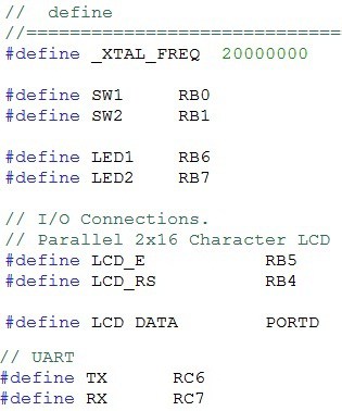
#define _XTAL_FREQ 20000000
Besides that, same step by #define the crystal frequency(_XTAL_FREQ) according to your external crystal frequency using. In here, the default external crystal frequency using are 20000000 (20MHz).
#define SW1 RB0
In here, we have already define the switch on SK40C board as RB0. User are no need to define again in the main coding.
#define LED1 RB6
In figure above, using the code #define, we can replace the RB6 and RB7 as LED1 and LED2. By doing this, we can easily remember and the I/O port we are using.
#define LCD_E RB5
#define LCD_RS RB4
#define LCD DATA PORTD
Besides that, user are not required again to define the LCD pin for SK40C. User only required to include the system.h file. Further detail on LCD please refer to Project_2.
#define TX RC6
#define RX RC7
User are not required again to define the serial comunication (UART) pin for SK40C. User only required to include the system.h file. Further detail on UART please refer to Project_13.
void delay_ms(unsigned int ui_value);
Function prototype is the declaration of a function that omits the function body but does specify the function’s name, arity, argument types and return type. The symbol “ ; ” should put at the end of this line.
MAIN PROGRAM
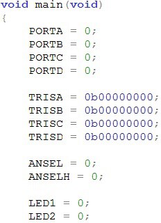
void main (void)
In figure above is the main program. 1st we have to type “void main(void)” at the 1st line to tell the micro-controller that this is the starting point of the program.
Here, void main, tell the compiler the name of the functin which is main and it don’t return any data(void).
PORTA = 0;
Clear the PORT to prevent from the data latch on the PIC MCU.
TRISA = 0b00000000;
is the Tri-STATE Register that declare the I/O ports as an INPUT or OUTPUT by (1=INPUT) and (0=OUTPUT). E.g. TRISB = 0b00001111 is to set the PORTB<7:4> to OUTPUT and PORT<3:0> as INPUT.
LED1 = 0;
Then, we make the LED1 off by giving it a 0 at initial state as show above. So as the LED2 too. To make it on, just change the 0 to 1.
ATTACHMENT
 International
 Singapore
 Malaysia
 Thailand
 Vietnam
