Your shopping cart is empty!
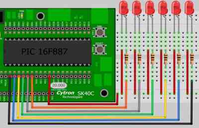
In project 1, you are about to experience how to program a LED chaser which can be increase the running speed by just a single button pushing. While releasing it, the running speed will slowly back to normal. In here, we are going to use total of 6 LEDs and will connected with a current limiting resistor before plug into the I/O port.
COMPONENT NEEDED
CONNECTION
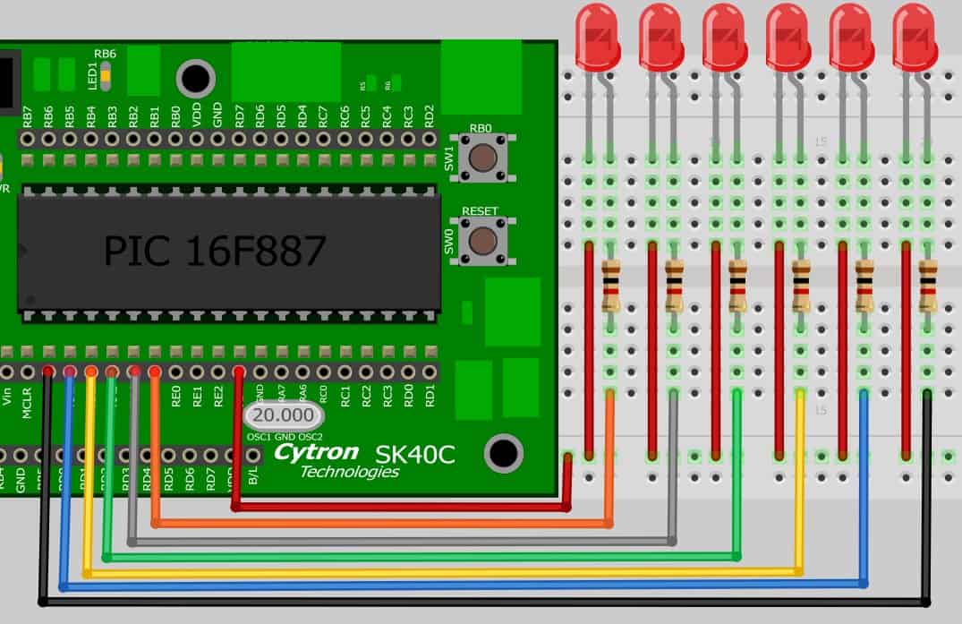
Refer to the figure below and connect the anode (+ve) of all LEDs to 1K Resistor and end of resistor is connected to the VDD (Power Supply). On the other hand, the cathode(-ve) of all LEDs are directly connected to the PORTA.0 until PORTA.5. Besides that, we are going to use the switch 1 (SW1) on SK40C as our running speed controller.
The 1K Resistor are function to limit the current going through it to the safe value. So that it can protect the LEDs from burn out.
ADDITIONAL INFORMATION
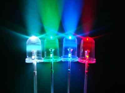
LIGHT EMITTING DIODE
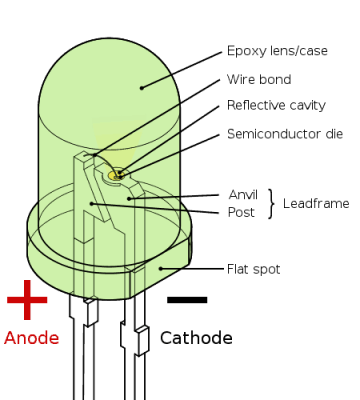
There are few method to determine the anode and cathode side of the LED such as :
1. The flat spot on the lens/case of the LED is cathode.
2. The short lead (or leg) is cathode.
3. The flag symbol inside the lens is cathode.
For further information about LED, please refer to this webpage.
RESISTOR COLOUR CODE
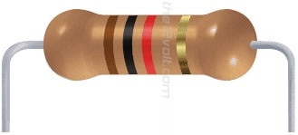
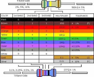
Above are the example of resistor with the colour code example. For more detail, refer to this webpage.
BREADBOARD OVERVIEW
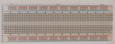
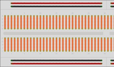
Figure above have shows that the connection of half of the breadboard. The RED and BLACK colour line are usually been connect to power supply (VDD) and ground (GND). They are connected all the way from the beginning to the end but they did not connect to each other.
Besides that, the orange colour line are the part that we usually use to place the electronic component. They are connected in a straight line.
There is a gap in the middle of the breadboard which are not connected to anything. This allow you to put integrated circuit across the gap and have each pin of the chip go to the different set of holes and therefore a different rial.
CODE OVERVIEW
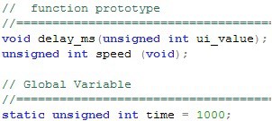
static unsigned int time = 1000;
As we can see that there is a static in front of the unsigned int. Static is a keyword which are commonly use in C programming to represent some value. Besides that, the value in static can be modified or replace. In here, we default the time value as 1000ms. For further information, please refer this webpage.
LED1 = 0;
Our main program are start with a while loop so that it can stay running non-stop. Refer to the connection circuit, the LEDs are connected to VDD at anode while the cathode is connected to the PORTB. So it means that to ON the LEDs, we need to give it a LOW bit (0). To OFF the LEDs, just simply give a HIGH bit (1) to LED1.
delay_ms(delay_period());
To control the running speed, we have give a value to delay_ms loop by scanning through the delay_period(). The delay_period() loop will give a value to delay_ms on how many millisecond should the be delayed.
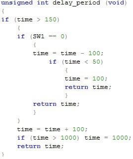
if (time > 150)
As we declare on the start that time is set to 1000ms at the beginning. In this if loop, we check that is it true that the time is greater (>) than 150ms. if is true, then do the following code, if not then out of this loop.
if (SW1 == 0)
If switch 1 is press, then do the subtraction of the time. if not then go to do the addition of the time.
time = time – 100;
In this case, it means that the default time 1000 is subtract by 100ms at each time the compiler come back to this subroutine.
If (time < 50)
{
time = 100
}
In this case, the time is check again whether the time is lesser (<) then 50ms. If it does, then change the time to 100ms. This is to prevent that the delay are too little and running speed too fast until we can’t seen.
return time;
As we have discuss before this, the value of static unsigned int time can be change or modified. In this code, after the time is been substrate or addition, it will return and change the value of time to become a new value.
time = time + 100;
{
if (time > 1000) time = 1000;
}
If the switch 1 is not press, the time will be increase by 100ms at the time. Besides that, after increase, it will be check again whether the time is greater then 1000ms. If it does, then limit it to 1000ms.
 International
 Singapore
 Malaysia
 Thailand
 Vietnam
