Your shopping cart is empty!
PROJECT 12
7 SEGMENT DISPLAY WITH CD4511 ENCODER
| Back to Project 11 | Go to Project 13 |
Besides on directly connected 7 segment with direct I/O port from microcontroller, we can also use the CD4511 (7 segment encoder) to help on decreasing the microcontroller I/O port and only required to send the binary data.
———————————————————————————————————————————————————-
COMPONENT NEEDED
———————————————————————————————————————————————————-
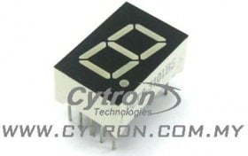 | (Common Cathode) |
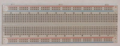 | |
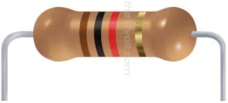 | |
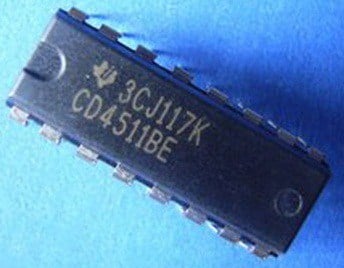 | CD4511 7 SEGMENT ENCODER |
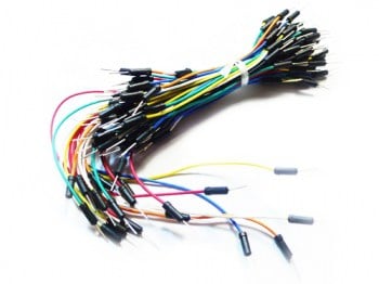 |
———————————————————————————————————————————————————-
CONNECTION
———————————————————————————————————————————————————-
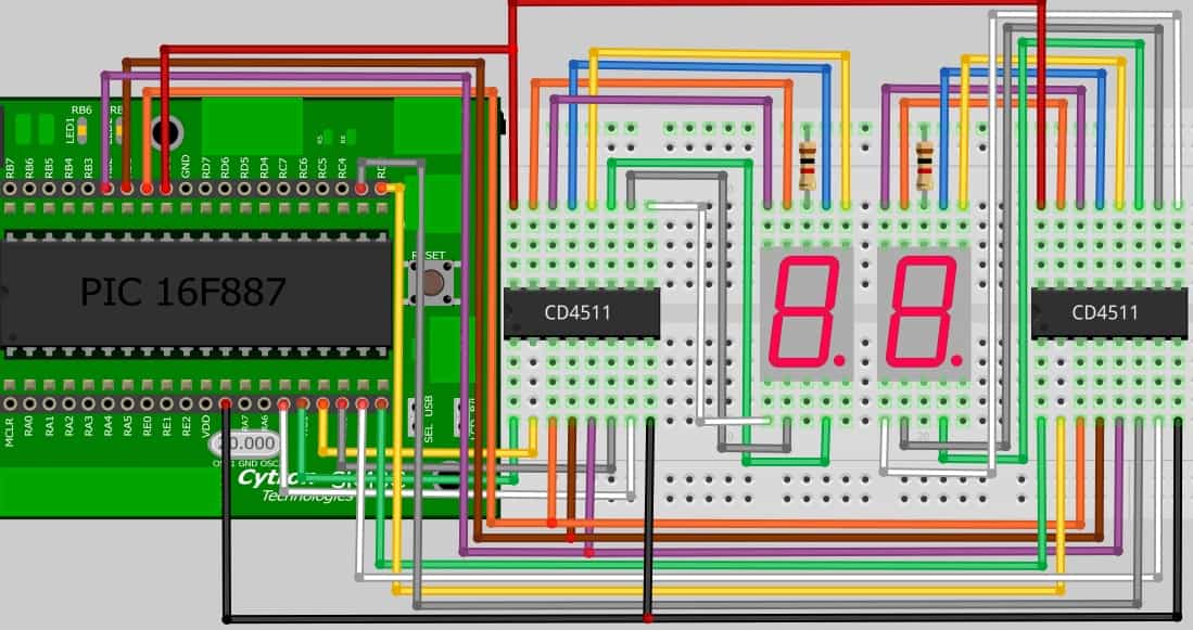
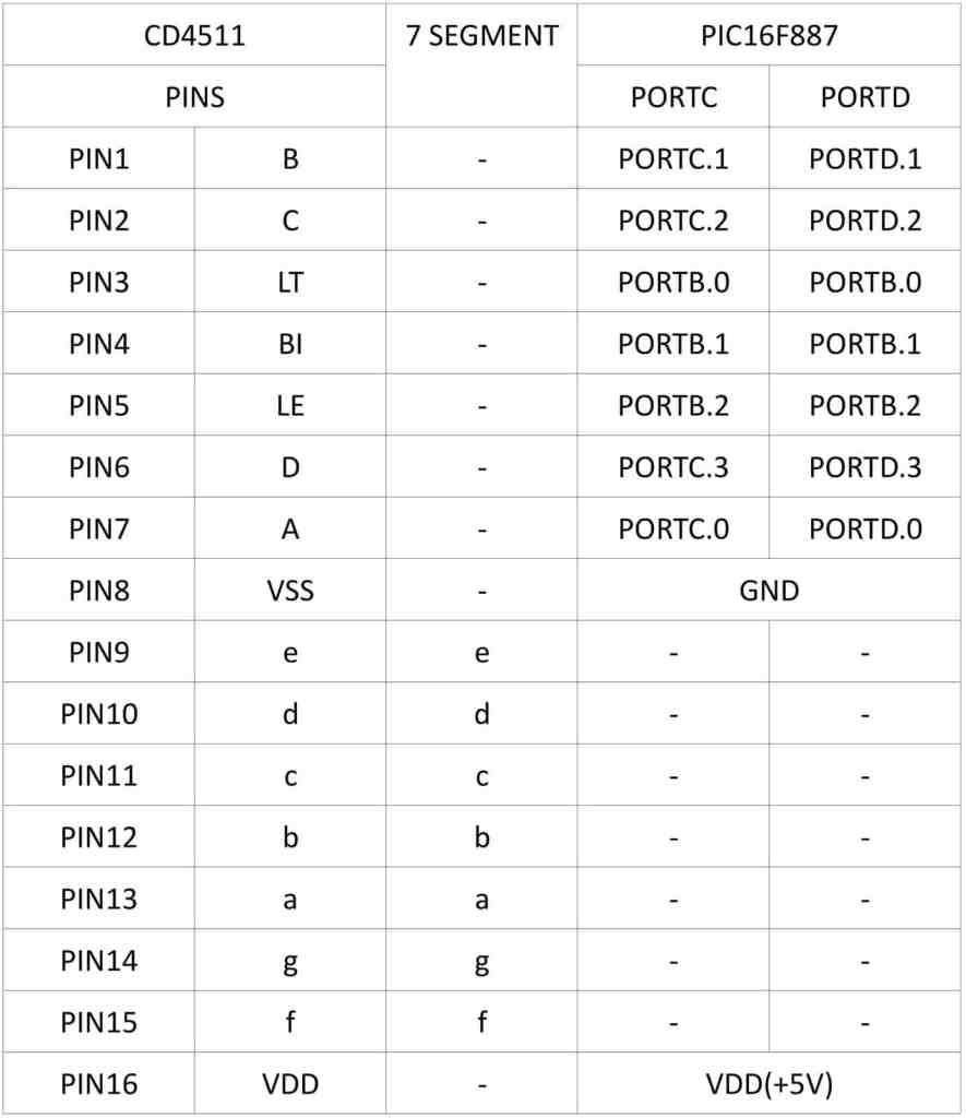
Referring to the figure below, RED and BLACK wire are VDD and GND and are share to both CD4511 encoder. Besides that, the LT, BI, LE pin from CD4511 are share to the same port of PIC MCU which is PORTB.0 , PORTB.1 and PORTB.2. Lastly, the LEFT CD4511 binary input (A,B,C,D) are connected to PORTC.0 until PORTC.3. While RIGHT CD4511 binary input (A,B,C,D) are connected to PORTD.0 until PORTD.3.
FROM CD4511 TO 7 SEGMENT & PIC16F887
———————————————————————————————————————————————————-
ADDITIONAL INFORMATION
———————————————————————————————————————————————————-
CD4511 7-SEGMENT ENCODER
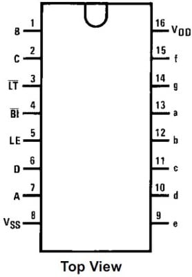
Figure above is the CD4511 7 segment encoder which use to encode the binary input given and convert it into 7 segment number. This Integrated circuit input are required the BCD code and it will display the number from 0 – 9 in 7 segment.
TRUTH TABLE
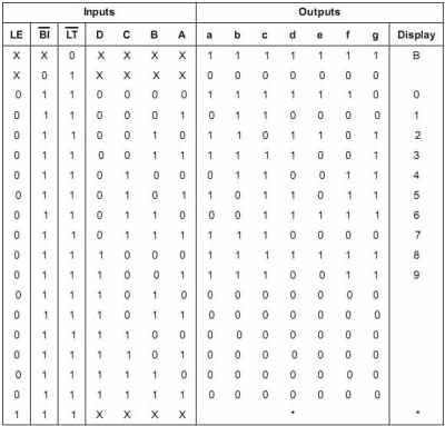
X = Don’t Care
*Depends upon the BCD code applied during the 0 to 1 transition of LE.
Above are the truth table for CD4511 encoder to convert the input BCD to output of 7-segment number.
———————————————————————————————————————————————————-
CODE OVERVIEW
———————————————————————————————————————————————————-
system.h
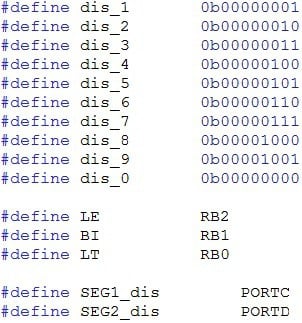
#define dis_1 0b00000001
Declare the BCD number that will send to the CD4511 encoder. E.g: 0b00000001 are number “1” in 7 segment.
#define LE RB2
#define BI RB1
#define LT RB0
In here, we have initially declare the I/O port that use to control the CD4511 such as lamp test(LT), blanking (BI), latch enable(LE) and store a BCD code.
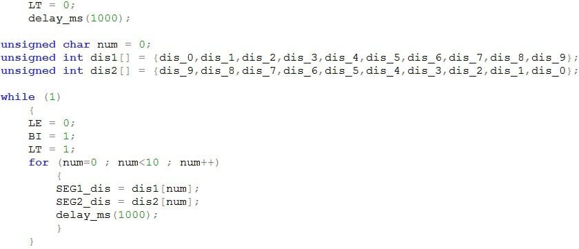
LT = 0;
Referring to the truth table, HIGH(1) the LT will stop the lamp test while LOW(0) the LT will on the lamp test.
LE = 0;
HIGH(1) to ON the latch enable and may store a BCD code. LOW(0) will OFF latch enable and will not store a BCD code.
BI = 1;
HIGH(1) will OFF the blanking and LOW(0) will ON the blanking.
| Back to Project 11 | Go to Project 13 |
———————————————————————————————————————————————————-
 International
 Singapore
 Malaysia
 Thailand
 Vietnam