Your shopping cart is empty!
PROJECT 10
DRIVING DC BRUSH MOTOR WITH MD10C
| Back to Project 9 | Go to Project 11 |
MD10C is an enhanced version of the MD10B which is designed to drive high current brushed DC motor up to 10A continuously. It offers several enhancements over the MD10B such as support for both locked-antiphase and sign-magnitude PWM signal as well as using full solid state components which result in faster response time and eliminate the wear and tear of the mechanical relay.
———————————————————————————————————————————————————-
COMPONENT NEEDED
———————————————————————————————————————————————————-
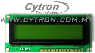 | 16 x 2 LCD Display |
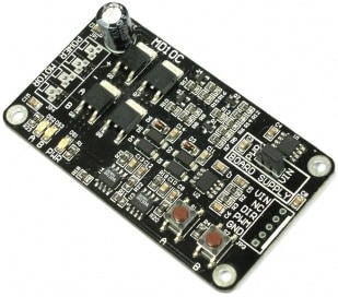 | MD10C |
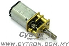 | DC MOTOR |
 | JUMPER WIRES |
———————————————————————————————————————————————————-
CONNECTION
———————————————————————————————————————————————————-
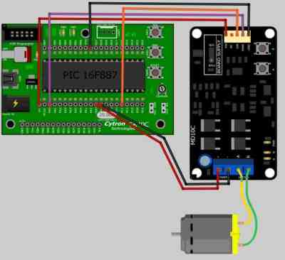
This latest MD10C have offer for both Sign-Magnitude PWM and Locked-Antiphase PWM mode. The only difference between these 2 mode connection are Sign-Magnitude PWM use 2 control signal while Locked-Antiphase PWM use only 1 control signal. Please refer MD10C datasheet.
SIGN-MAGNITUDE PWM
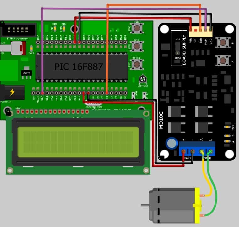
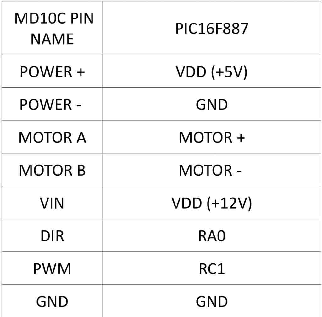
For sign-magnitude PWM operation, 2 control signals are used to control the speed and direction of the motor. PWM is feed to the RC1 pin to control the speed while DIR pin is used to control the direction of the motor. Please refer figure and table below for Sign-Magnitude PWM connection.
LOCKED-ANTIPHASE PWM
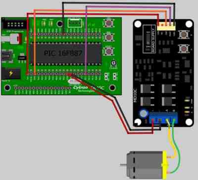
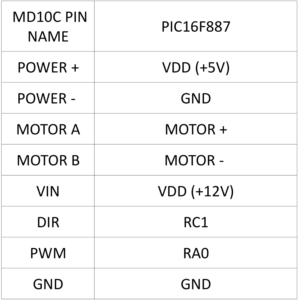
For Locked-Antiphase PWM operation, only 1 control signal is needed to control the speed and direction of the motor. PWM pin is connected to logic high while the DIR pin is being feed with the PWM signal. When the PWM signal has 50% duty cycle, the motor stops running. If the PWM has less than 50% duty cycle, the motor will turn CW (or CCW depending on the connection). If the PWM signal has more than 50% duty cycle, motor will turn CCW (or CW depending on the connection). Please refer figure and table below for Locked-Antiphase PWM connection.
———————————————————————————————————————————————————-
ADDITIONAL INFORMATION
———————————————————————————————————————————————————-
MD10C – ENCHANCED 10A DC MOTOR DRIVER
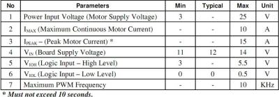
The MD10C has been designed with the capabilities and features of:
• Bi-directional control for 1 brushed DC motor.
• Support motor voltage ranges from 3V to 25V.
• Maximum current up to 10A continuous and 15A peak (10 second).
• 3.3V and 5V logic level input.<
• Solid state components provide faster response time and eliminate the wear and tear of mechanical relay.
• Fully NMOS H-Bridge for better efficiency and no heat sink is required.
• Speed control PWM frequency up to 10KHz.
• Support both locked-antiphase and sign-magnitude PWM operation.
• Dimension:75mm x 43mm
JUMPER – BOARD SUPPLY SELECTOR
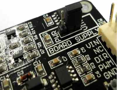
PWR : Board is powered by motor power input. Only select this when motor power input is > 14V.
VIN : Board is powered by VIN. 12V must be supplied to the VIN pin and motor power input can be 3V to 25V.
SPG10 – METAL GEARMOTOR
There are 3 types of metal gear motor which come with the difference gear ratio, stall torque and free run RPM. Please refer to SPG10 datasheet for detail.
———————————————————————————————————————————————————-
CODE OVERVIEW
———————————————————————————————————————————————————-
MAIN PROGRAM
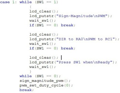
sign_magnitude_pwm();
Call and execute “sign_magnitude_pwm” subroutine.
pwm_set_duty_cycle(0);
Set PWM duty cycle to 0.
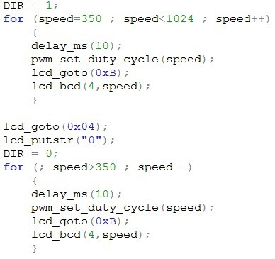
DIR = 1;
Set the motor spinning direction. HIGH(1) to CW, LOW(0) to CCW.(Depend on motor connection)
for (speed = 350;speed<1024;speed++)
Increase the speed by 1 at the time which started from 350 until 1024.
pwm_set_duty_cycle(speed);
Send the speed to the pwm duty cycle to generate the PWM.
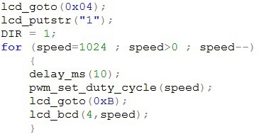
for (speed=1024;speed>0;speed–)
Decrease the speed by 1 at the time started from 1024 until 0.
SWITCH 1 PRESS CHECK
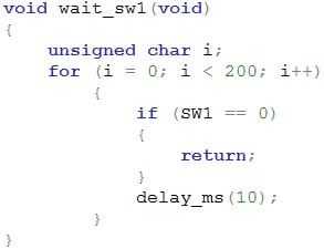
Check if switch 1 is press by continuously loop for 200 times.
PWM INITIALIZE
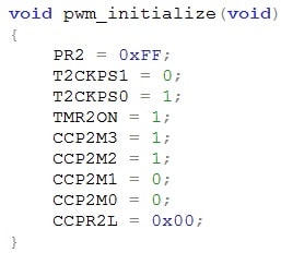
PR2 = 0xFF;
Send the timer 2 value(PR2) as 0xFF.
T2CKPS1 = 0;
T2CKPS1 = 1;
Set timer 2 prescaler to 1:4.

TMR2ON = 1;
HIGH(1) to Timer 2 ON, LOW(0) to Timer 2 OFF
CCP2M3 = 1;
CCP2M2 = 1;
CCP2M1 = 0;
CCP2M0 = 0;
Configure the CCP2 module as PWM mode.
CCPR2L = 0x00;
Initialize the PWM duty cycle at 0 at the start time.
PWM DUTY CYCLE
CCP2CON<5:4>
These bits are the two LSB of the PWM duty cycle.
CCPR2L = ui_duty_cycle >> 2;
These are the 8 MSB of the PWM duty cycle.
| Back to Project 9 | Go to Project 11 |
———————————————————————————————————————————————————-
 International
 Singapore
 Malaysia
 Thailand
 Vietnam
