 International
 Singapore
 Malaysia
 Thailand
 Vietnam
Your shopping cart is empty!

Reading Analog Signal Using MCP3008 On Raspberry Pi
- Idris Zainal Abidin
- 14 Nov 2018
- 789
INTRODUCTION
Maybe you’re not interested to write 2 different program on 2 different controller platform as shown in I2C Raspberry Pi Arduino – Reading Analog Signal. Another option, you can read the analog signals using MCP3008 (Analog to Digital – SPI) on Raspberry Pi. This tutorial will show you how.
VIDEO
This video shows how to read analog signals using MCP3008 on Raspberry Pi.
HARDWARE PREPARATION
- Raspberry Pi Zero WH (with Header)
- Maker pHAT
- MCP3008 - Analogue to Digital Converter
- I2C 1602 Serial LCD
- Breadboard 8.5x5.5cm
- Temperature Sensor (Celsius)
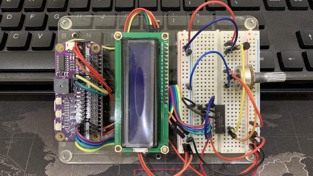
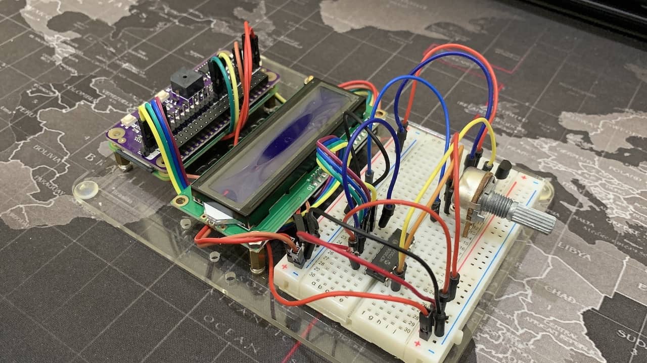
Wiring Connection
1. MCP3008
| MCP3008 Pins | Connections |
| 1 (CH0) | Potentiometer analog signal pin |
| 2 (CH1) | LM35 analog signal pin |
| 3 (CH2) | |
| 4 (CH3) | |
| 5 (CH4) | |
| 6 (CH5) | |
| 7 (CH6) | |
| 8 (CH7) | |
| 9 (DGND) | GND (Maker pHAT) |
| 10 (CS/SHDN) | CE0 (Maker pHAT) |
| 11 (DIN) | MOSI (Maker pHAT) |
| 12 (DOUT) | MISO (Maker pHAT) |
| 13 (CLK) | SCLK (Maker pHAT) |
| 14 (AGND) | GND (Maker pHAT) |
| 15 (AREF) | 3.3V (Maker pHAT) |
| 16 (VDD) | 3.3V (Maker pHAT) |
2. Potentiometer
| Potentiometer Pins | Connections |
| 1 | 3.3V (Maker pHAT) |
| 2 | CH0 (MCP3008) |
| 3 | GND (Maker pHAT) |
3. LM35
| LM35 Pins | Connections |
| 1 | 5V (Maker pHAT) |
| 2 | CH1 (MCP3008) |
| 3 | GND (Maker pHAT) |
Software Preparation
First, you need to enable I2C and SPI module in Raspberry Pi. Then instal MCP3008 library from Adafruit. Write following command on Terminal.
sudo apt-get update
sudo apt-get install build-essential python-dev python-smbus git
git clone https://github.com/adafruit/Adafruit_Python_MCP3008.git
cd Adafruit_Python_MCP3008
sudo python setup.py install
Sample Code
This is the sample code to display calculated data on I2C LCD.
Thank you
References
Thanks for reading this tutorial. If you have any technical inquiry, please post at Cytron Technical Forum.
Related Products
")
LM35 Temperature Sensor (Celsius)
$2.00 $2.00
x 1 unit(s)

I2C 1602 Serial LCD for Arduino & RPI
$2.75 $2.75
x 1 unit(s)

4 In 1 MAX7219 Dot Matrix Display Module
$6.25 $6.25
x 1 unit(s)

MCP3008 - Analogue to Digital Converter
$4.88 $4.88
x 1 unit(s)

Maker pHAT: Simplifying Raspberry Pi for {Educa...
$10.90 $10.90
x 1 unit(s)